.jpg?height=200&name=Mastering%20Bandpass%20Filters%20(A%20Guide%20for%20RF%20and%20Electrical%20Engineers%20in%20Military%20and%20Aerospace).jpg)
Surveillance and reconnaissance, covert operations, space exploration. These aren't simply sci-fi...

As Burt Rutan once said, “Testing leads to failure, and failure leads to understanding.”
With a custom bandpass filter design, testing is a key part of the process. Only with rigorous testing can we establish if it will operate effectively when deployed, even if the environmental conditions are harsh. Once we know what fails, only then can we ensure it’s fixed.
It’s this rigorous testing that gives us the confidence that our bandpass filters will work at a high quality and according to your specifications.
But how does our RF manufacturing team test these filters, and how often do these tests happen for one RF bandpass filter? To answer these questions, we walk you through the types of testing we conduct in our U.S.-based filter manufacturing facility.
5 Types of Environmental (ESS) Testing for Custom Bandpass Filter Designs
Not all bandpass circuits will go through every testing process. But to provide 100% transparency for our process, here are the five major types of tests that normally occur:
1. Temperature Cycling
In temperature cycling tests the objective is to test every part of the bandpass filter and make sure that any changes in temperatures don’t affect the structure or its materials. Sometimes custom designs come with specific requirements that filters need to undergo testing for. This is to establish that the filters are stable and will continue to operate even in extreme temperatures.
An example of this testing is cycling the temperature from -55 degrees Centigrade all the way up to 125 degrees Centigrade. This is done in equipment that is essentially an oven or freezer. The cycle testing exposes the bandpass filters to extreme temperatures and everything in between.
Typically the testing will run through five cycles spending approximately 30 minutes at each cycle, but we have availability at all types of ranges – from five minutes per cycle or 30 minutes for 100 cycles! It all depends on what you need.
2. Vibration Testing
Typically this type of testing is done when bandpass filters are attached to aircraft or other forms of transport vehicles. Traveling at high speed produces vibrations which can dislodge components or connections. The test is conducted to make sure that the active bandpass filter schematic can withstand vibrations and will continue to operate even when attached to jet airplanes, for example.
Vibration testing is not conducted on all bandpass filter designs, rather it is dependent on the customer and the application. It’s a more common test for filters that will be attached to different forms of military bandpass filtering applications rather than commercial use.
The testing machine our engineers use looks like a giant stereo system that has been placed on its side. This is known as a vibration “head.” The bandpass filter is mounted to the top of it. For the test, the vibration table shakes the filter aggressively. After the test, the unit is plugged into a system to confirm that it still works and hasn’t been impacted by the vibration.
3. Burn-in Testing
The objective of burn-in testing is to ensure that none of the bandpass filter components have random failure. This is not a common test and is usually only conducted on filters or circuits that require extremely high-powered or prolonged periods of usage. The test can indicate if there are any intermittent failures in specific parts.
The test is quite simple. The filters are attached to a power supply and left on for a very long period of time. The period could range from 72 hours or up to ten days. If additional testing is required, it might be placed in an oven during that time to test for temperature resilience as well.
4. Leak Testing
Sometimes filters need to be hermetically sealed to protect them from exposure to high humidity or high altitude. We use a laser sealing process that ensures that no gas or liquids can get inside or out of the unit.
The tests are conducted to make sure that there are no defects in the seal.
5. Frequency testing
General frequency testing is conducted on the bandpass filter design using a network or spectrum analyzer. For the test, the unit is plugged in to see how it responds as different frequencies are scanned. Once it is confirmed that the unit is reading across its designated frequency range, additional tests are conducted to fine-tune it to specific bandpass filter cutoff frequencies.
At Q Microwave, we have developed our own frequency testing that is especially important to custom bandpass filter designs. This test checks if the unit operates within and reads the frequencies it’s been designed for. The required parameters are set and then the test evaluates the actual response of the unit with a simple pass or fail.
If this test results in a failure, then some fine-tuning will be required. This may involve adjusting the coils so that the right connections meet. Alternatively, the structure may need to be adjusted to ensure that the correct frequencies are being met. Once the fine-tuning is completed the bandpass filter is sent through Q Microwave’s testing again until it achieves the desired pass.
Final Bandpass Filter Design Testing and Inspection
The bandpass filter prototype needs to go through all the specified individual tests and achieve a pass in each. It is then cleaned and sealed before it can undergo final testing and inspection.
The cleaning is an essential part of the process that ensures no dust or foreign materials are trapped within the unit which could impact the filter’s performance. It is also why it’s only cleaned after being built. Spot cleaning is done with a tiny brush and an alcohol solution.
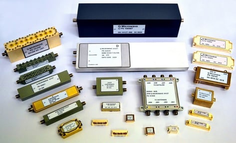
Sample of Q Microwave’s RF filters.
A deeper clean is completed with a water and solvent mixture. The filter will be dipped in the solution and agitated. Most unwanted materials are not water soluble and will wash off in the process.
With cleaning completed the unit moves on to final testing and inspection. The final testing ensures that all of the custom bandpass filter design requirements have been met. The inspection confirms this by checking all the boxes in the design, building, and testing documents.
The inspector also has to confirm that the label is correct and contains Q Microwave’s details as well as the client-specified details. Only once all of this has been completed and confirmed to be correct, can the filter be shipped.
If you want to learn the other steps for how a bandpass filter schematic is turned into an RF filter, check out this article.
Still Have Questions on Our Bandpass Filter Design Procedures?
While we sell quality, off-the-shelf bandpass filters, we do a great deal of custom designs as well. For those custom needs, testing is an essential part of the process to ensure that the units meet your initial requirements.
Find out more about our bandpass filter services! There you can learn more about our bandpass filter offerings and why we are trusted industry leaders in RF engineering.